Environments vary substantially between computers, so you’ll often see environment-specific code hidden in the PEEKs and POKEs of old BASIC programs.
We’ll take a brief tour of the Ohio Scientific and Commodore 64, two computers from the late 1970s to early 1980s.This article will give pointers to supporting material, so we can still glean lessons from the old software.
Ohio Scientific (OSI)
The OSI machines were fairly popular for their time. The Model 500 came out in 1977, but by 1982 OSI had been sold, shifted focus, and changed its name.
Characters
Characters are numbered 0..255.
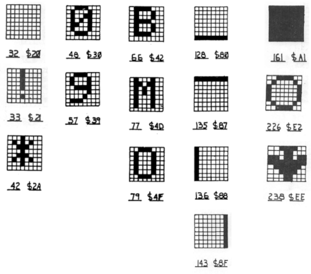
Notice that the letters and symbols have a blank rightmost column and bottom-most row. There’s no kerning control on these:)
Here are the other character categories:
| Range | Shapes |
| 0-31 | Misc. shapes: cars, ships, arrows, … |
| 32-122 | Same as ASCII: symbols, numbers, upper- and lower-case letters |
| 123-127 | { } | ➗ ~. (Normal ASCII would be { | } ~ DEL.) |
| 128-178 | Drawing aids: lines for each row and column, squares in various positions within the character, and diagonals |
| 179-182 | Halves of a ship or submarine |
| 183-187 | Various checkerboards |
| 188-210 | Drawing aids: mostly diagonals and corners |
| 211-214 | Halves of an airplane |
| 215-219 | Crossings: T and + |
| 220-228 | Balls, full and partial |
| 229-255 | Variety of shapes: hearts, planes, tanks, etc. |
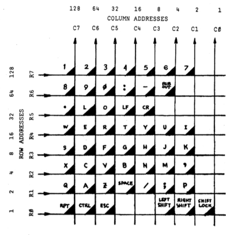
Keyboard
The keyboard is set up as a matrix.
There is a BASIC routine that typically runs, which looks for ^C (as a break key) while you’re running. You turn this off by POKE 530, 1, and turn it back on with POKE 530, 0.
Many games want to poll the keyboard directly. Doing this is a two-step process:
POKE 57088, R
C = PEEK(57088)
That is, this memory address turns on the specified keyboard rows when it’s written, and reads the column when it’s read.
Just to keep things fun, some models use positive logic – set the flag corresponding to the rows/columns you want to use; others use negative logic – set the flag for the rows/columns you don’t want to use.
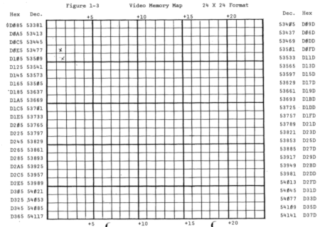
Screen
Screen memory is allocated as a 32×32 block, starting at 0xD000. However, only the middle 24 lines and columns are visible. These start at 0xD085. This is due to limitations of the circuitry, and to use of analog TVs for display.
At 24×24, you only have 576 bytes visible, for a screen resolution of 192×192 pixels. Later machines could use the full 32×32 space, for 1024 bytes on-screen and 256×256 resolution.
To reference the screen at (row, column), with row in 0…23 and column in 0…23, you use the address:
53381 + (row * 32) + column
When you poke a byte into a screen memory address, that character indexes the character generator ROM. That looks up the 8 bytes of character data, which feeds to the display circuitry.
Commodore 64 (C64)
Despite being only five or so years newer, the C64 is substantially more complicated.
The Commodore 64 Programmer’s Reference Guide (see References; C64PRG from here out) gives pretty complete information about it. It was a popular enough machine that an internet search will give you plenty more material.
This machine has much more depth, and much more “accidental complexity”. Rather than attempt full descriptions, I’ll give an overview and point to C64PRG for more details.
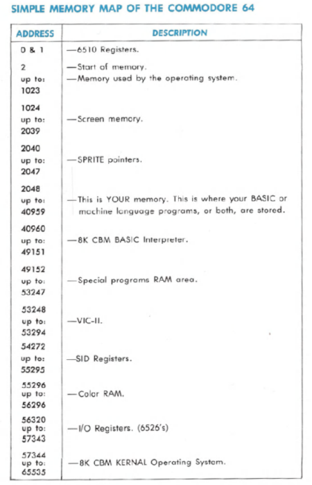
Memory Map
The memory is broken up into major regions – for the screen, sprites, user memory, various chips, color RAM, etc. A simple map is on C64PRG p. 212, with more detailed maps on pp. 260-272.
Characters
There are two built-in character sets, and you can create your own in RAM. See Appendix B of C64PRG, p. 376, for the character sets, and pp. 103-108 for instructions on how to use them.
As with OSI, characters are in an 8×8 grid.
Set 1 has @ at 0, A-Z at 1-26, 0-9 at 48-57 (as for ASCII), other symbols and a few graphics sprinkled through the rest up to 127. There are no lowercase letters in this set.
Set 2 has lowercase letters a-z at 1-26 and uppercase letters at 65-90 (where they would be in ASCII). There are four graphic symbols, and a lot of unused space (surprisingly).
For both sets, the values 128-255 correspond to the characters 0-127, but with foreground and background reversed.
If these characters aren’t enough for you, you create a character set in RAM. For that, you must set up (or copy in) all characters you want to use. C64PRG pp. 108-114 has details and examples.
Keyboard
There are several ways to get keyboard input.
At BASIC level, INPUT reads a line, while GET returns one character at a time.
To read the currently pressed key, use PEEK(197). This is translated to correspond to the ASCII character. Page 93 of C64PRG describes this (page 93 and Appendix C starting on page 379).
There’s a fourth way too. As for the OSI machine, you have direct access to the keyboard matrix. POKE 56320, C – write the columns to scan, then R = PEEK(56321) will return the rows that are active. (See C64PRG, p. 94.)
Here is the keyboard matrix:
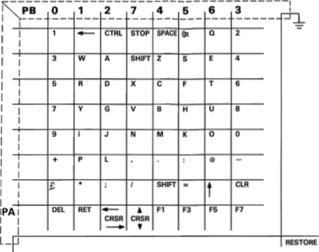
Notice that the columns are labeled in a random order, and the rows aren’t labeled at all.
Screen
The C64 screen is mapped to memory, from locations 1024 to 2023: 1000 visible locations (25 rows with 40 columns). The screen location can be changed
Since each character is 8 bits across, the resolution is 320×200. I don’t know if C64 was the first to use that resolution, but multiples of it are still in use: 640×400 was common for a while, and 1280×800. My monitor also has settings for 1920×1200, 2560×1600, and 3840×2400, all derivatives.
There is also color memory, from 55296 to 56295. (Each cell of color memory corresponds to a character in screen memory.) Unlike the screen memory, these locations cannot change. You can poke one of 16 values in each color memory cell to set the corresponding character color.
That standard mode is one of several graphics modes. (See C64PRG, Appendix N, 6566/6567 (VIC-II) Chip Specifications, pp. 436-456, for full details.)
Multi-color mode (C64PRG, pp. 115-119) lets you assign 2 bits to choose between screen color, two background colors, or a standard color in the range 0..7. The first three cases are set by pointing to a particular cell, so you can change all of them at once. Unfortunately, it works two horizontal pixels at a time.
Extended background color model (pp. 120-121) lets you control the background color of each character, but limits the size of the character set to 64 characters.
Bit-mapped graphic mode (pp. 121-127) lets you set each individual bit (of the 320×200 grid) to a foreground or background color. Or, you can have a 160×200 multi-color bit-map (pp. 127-128), reminiscent of standard multi-color mode.
If you’re willing to work at it, you can use different graphics modes in different vertical sections of the screen, by altering the mode during the vertical blanking interval (while the CRT is moving from one line to the next).
Sprites
Sprites are special graphic images that can be easily relocated on the screen. Think of a 2-1/2D animation, where different layers slide around independently. You have 8 sprites to work with, although I believe you can also play tricks by changing their values while they’re drawn (during the vertical blanking interval). (C64PRG 131-149, 153-181; Appendix N, 6566/6567 (VIC-II) Chip Specifications, pp. 436-456.)
A sprite is 24 dots horizontally by 21 dots vertically. It can be displayed at that size, at double width, double height, or both. It can be instantly hidden.
Sprites can either be binary, with a 1 showing the foreground color (specific to each sprite) or a 0 indicating it’s transparent. Or, you can have a multi-color mode (similar to the screen one) where you use 2 bits horizontally to specify one of four colors.
Sprites can be positioned to specific pixels (although the range is somewhat limited). Each sprite has its own depth; when they overlap, their transparent bits may reveal an underlying sprite or background. Lower number sprites are in front, and you can control whether sprites are in front of or behind the background.
Finally, sprites have collision detection: when sprites collide with each other (on non-transparent parts) or with the background, registers mapped to memory locations will set bits reflecting that. By peeking at 53278, you can see which sprites have collided with each other. At 53279, you can check which have collided with the background.
You can see how sprites would be very handy for certain kinds of games.
Sound
The C64 has a synthesizer built in (C64PRG pp. 183-208):
- Three voices: 16 bit frequency (set in two bytes)
- ADSR – attack, decay, sustain, release (shaping volume)
- Filtering
- Ring modulation
- White noise
The sound chip maps its registers to memory starting at address 54272.
There’s a table of note values (high and low frequencies) in Appendix E, pp. 384-386, and filter settings, p. 387.
Finally, there’s a full reference in C64PRG, Appendix O, 6581 Sound Interface Device (SID) Chip Specifications, pp. 457-481.
Conclusion
It’s hard to separate old programs from their environment. Notably, many games use PEEK and POKE to access low-level settings.
We’ve looked at two machines. The OSI series started in 1977 (OSI) – 4K RAM (growing over the years), a limited 24×24 character screen, character graphics only, no fancy sound support. The Commodore 64 released in 1982: 64K RAM, flexible graphics, sound, many support routines.
In both cases, the complexity level is high – there are things the machine can do, but you have to work hard to set it all up. Compare that to now – many things are simpler because they can be done in software, and we have simpler abstractions. But now the complexity is there because there are so many alternatives, so many layers, so much variety.
References
Application
“Swarmed” – YouTube series – https://www.youtube.com/watch?v=OSMrjITJBbo&list=PL1KGt8huiT78vOXxrqL5_ZLQPevBeL4kw – demonstrates transliterating a game from 1980s BASIC into a more modern form.
“Transliterating Old-School BASIC,” https://xp123.com/articles/transliterating-old-school-basic/ – Retrieved 2021-07-20.
Commodore 64
C64/C64C Service Manual, https://archive.org/details/C64-C64C_Service_Manual_1992-03_Commodore/mode/2up . Retrieved 2021-07-17.
Commodore 1541 Disk Driver User’s Guide,
Commodore 64 Programmer’s Reference Guide, https://archive.org/details/Commodore_64_Programmers_Reference_Guide_1983_Commodore/mode/2up . Retrieved 2021-07-17.
Commodore 64 User’s Guide, https://archive.org/details/Commodore_64_Users_Guide_1982_Commodore . Retrieved 2021-07-17.
Ohio Scientific
Ohio Scientific, Inc. The 8K BASIC-in-ROM Reference Manual. 1978.
Ohio Scientific, Inc. The Challenger Character Graphics Reference Manual. 1978. Retrieved 2024-10-18.
Wikipedia. “Ohio Scientific”. Retrieved 2021-07-18.